Composting toilet scale model
From WaiWiki
This page is an extension of the page on composting toilets.
Parts
.
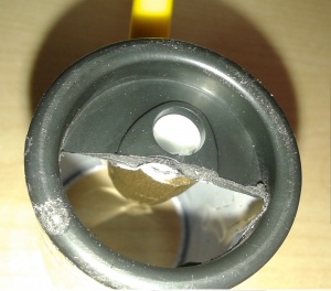
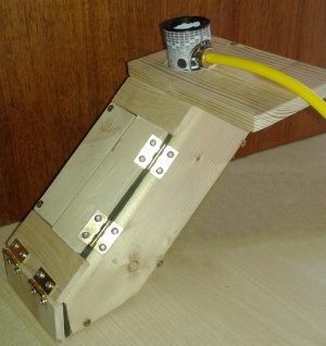
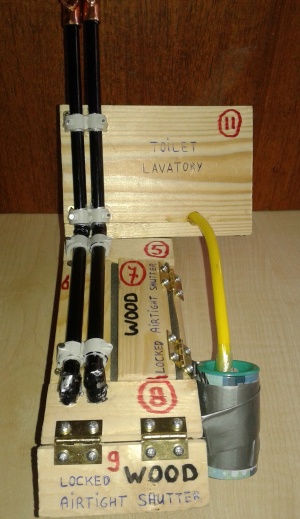
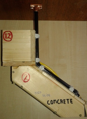
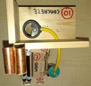
- The big hole (fecal hole) is for collecting faeces, which goes straight down to the floor of the slide
- The small hole (urine hole) in the toilet is for collecting and diverting urine
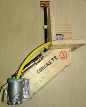
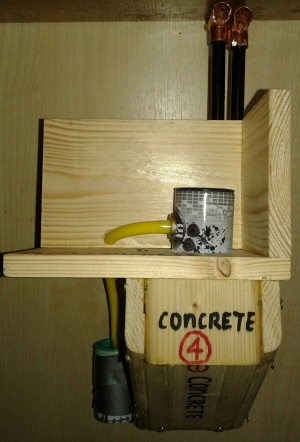
- The yellow tube is the tube that drains the urine from the toilet to the urine collection barrel
.
Additional Parts
- The urine collection barrel is placed at the downside of the slide.
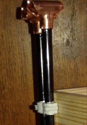
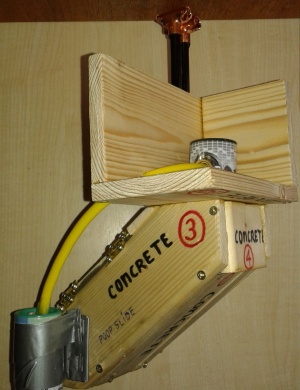
- The black pipes are for solar ventilation. They are metal / aluminium pipes that penetrate the cover of the slide at its downside, to suck up the relatively cold air that came in through the fecal toilet opening. The sucking draft is generated by the upwards movement of the air through the black pipes, caused by the heating of the pipes and the air inside through sunlight exposure. Relatively hot air goes up. Relatively cold air goes down. T-junctions are attached on the top-end of the ventilation pipes to let the air go out while preventing raindrops from coming in. The ventilation pipes are painted black to maximize heating by the sun. The total surface volume of the ventilation pipes (probably 3 or 4 pipes) needs to match the surface volume of the fecal hole to create optimal air draft.
.
The Numbered Parts
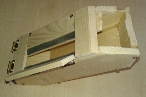
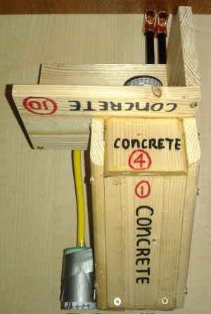
- 1 is the concrete bottom of the slide, measured as in between side 2 and side 3, which is 100 centimeter wide (in between walls). It is about 260 centimeter long. In reality, the sides 2 and 3 will be constructed on top of the concrete base (part 1), and for stability of the entire construction, the actual width of this base may be more than 120 cm.
- 2 and 3 are the concrete sides of the slide. Where connected to part 1, they are about 260 cm long. They may be 100 cm high.
- 4 is the back side of the concrete slide, on the upper side of the slide. It is about 100 cm high, and about 120 cm wide (100 + 10 + 10), depending on the thickness of the concrete blocks used for part 2 and 3. In reality, part 4 will be constructed on top of the concrete base (part 1), and the actual height of part 4 will therefore be closer to 50 cm.
- 5 is the upper part of the cover on the slide; either concrete or wood. It is about 120 cm wide (100 + 10 + 10), depending on the thickness of the concrete blocks used for part 2 and 3.
- 6 is the (wooden or concrete) part next to the inspection shutter that partly covers the slide. The ventilation pipes will run across 6.
- 7 is the inspection shutter that partly covers the slide. Isolation material needs to keep the slide air-tight (apart from the fecal hole and the ventilation pipes), to prevent unwanted air-draft
- 8 is the lower part of the cover on the slide; either concrete or wood
- 9 is the shutter at the bottom of the slide; for removal of the compost (end product). Isolation material needs to keep the slide air-tight (apart from the fecal hole and the ventilation pipes), to prevent unwanted air-draft
- 10 is the concrete floor of the lavatory cabin
- 11, 12, 13 and 14 are the walls of the lavatory cabin (13 and 14 do not exist in the pics)

